Diode Bridge Circuit Diagram Bridge Rectifier – Constructi
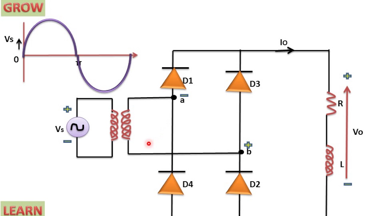
Full wave bridge rectifier – circuit diagram and working principle Solved for the diode bridge circuit shown, assume the diodes Bridge rectifier circuit explained
Bridge diode and schematic stock photo. Image of spare - 298040692
Diode bridge circuit diagram Single phase full wave rectifier circuit diagram Electrical – what happens if we take out two diodes from diode bridge
Full wave bridge rectifier download scientific diagram
Diode bridge rectifierDiode bridge circuit vector illustration concept stock vector (royalty Diode 24vRectifier diode circuit diagram.
Bridge diode 24v supply adapterHow to make 24v adapter or dc power supply easy at home Bridge diode and schematic stock photo. image of spareDiagram of a bridge rectifier.

Circuit diagram of full rectifier
Full wave rectifier and bridge rectifier theoryDiode bridge 486 รายการ ภาพ ภาพสต็อกและเวกเตอร์ Full wave bridge rectifier circuit diagramHow to make adjustable on delay timer 555 ic.
Diode bridge: how four diodes can convert from ac to dcWhat should i consider when choosing the right diode… How do rectifier diodes workWhat is the function of rectifier cheaper than retail price> buy.

Bridge rectifier circuit, construction, working, and types
Full wave bridge rectifier schematicBridge rectifier diagram and explanation Rectifier circuit diagramBridge rectifier – construction, working, advantages.
Diode bridge rectifier electrical4uBridge rectifier diagram and explanation Rectifier bridge diode rectifiers circuits13+ bridge diode diagram.

How to make 24v adapter or dc power supply easy at home
The full-wave bridge rectifier .
.


Bridge Rectifier Circuit, Construction, Working, and Types

Bridge Rectifier Circuit Explained
How to make 24v adapter or DC power supply easy at home

Diode Bridge Rectifier | Electrical4U

Full Wave Bridge Rectifier Circuit Diagram
Single Phase Full Wave Rectifier Circuit Diagram

13+ Bridge Diode Diagram | Robhosking Diagram

bridge rectifier diagram and explanation - IOT Wiring Diagram